Reaction wheel
Predictable and easy to control, but limited torque, and a high power draw to slew an agile spacecraft quickly.

Veoware Steering System
Control Moment Gyroscopes give a small satellite far more agility and torque than reaction wheels, but they need a smarter control layer to tame. Our turn-key steering system drives a full cluster across all three axes, so you don't have to.
Cluster-level rate steering · 3-axis torque · singularity avoidance
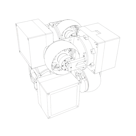
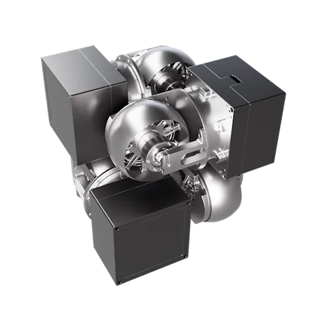
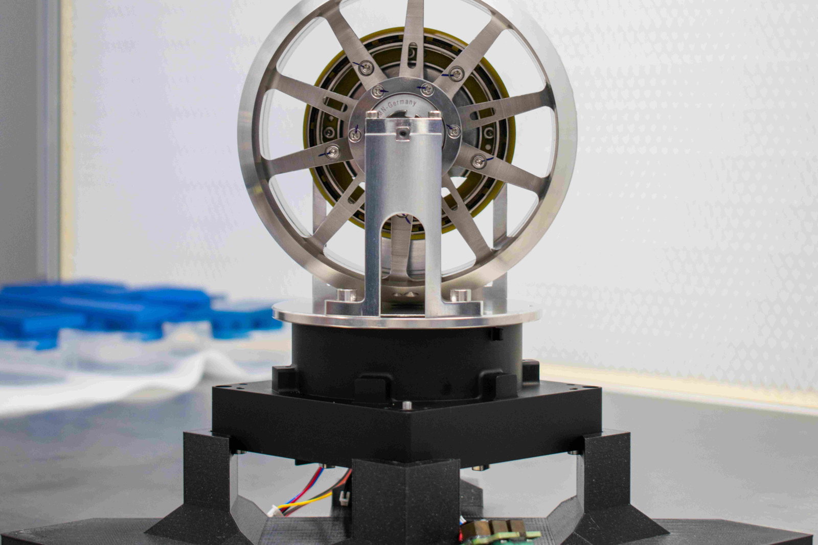
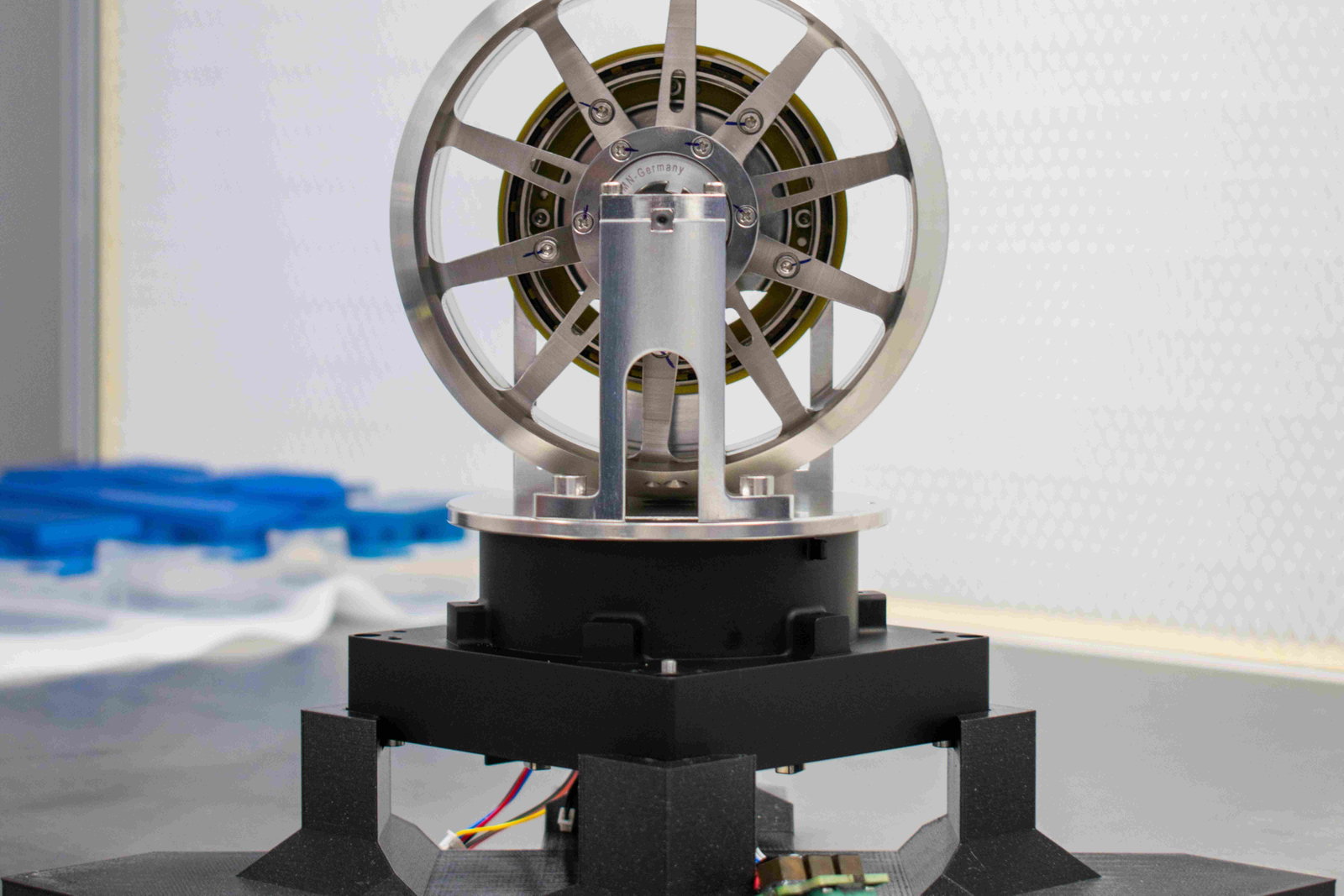
A reaction wheel is one-to-one: command an acceleration, get a proportional torque about that axis. A CMG spins a flywheel at constant speed and tilts it, so a tiny gimbal motion redirects a large stored momentum creating a large torque. Powerful, and the map from command to actuator is more complex — which is what the steering law is there to handle.
Predictable and easy to control, but limited torque, and a high power draw to slew an agile spacecraft quickly.

Exceptional torque for its size and power. But one torque can come from many gimbal motions, the mapping shifts as gimbals move, and certain geometries (singularities) momentarily lose authority. That is what the steering layer manages.
Your guidance and control loop keeps doing exactly what it already does, computing the body-frame torque the spacecraft should apply. Instead of mapping that to reaction wheels, it hands the requested torque to the Steering System, which owns everything downstream.
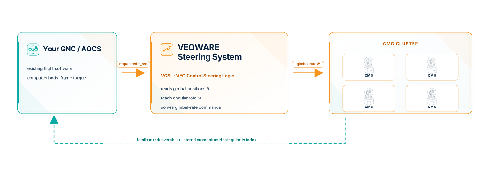
The requested torque in the body frame, plus the current gimbal positions and the spacecraft's angular rate.
The gimbal rates each CMG must execute to realise that torque, every control cycle.
The torque the cluster can actually deliver, its stored momentum, and how close it is to a singularity.
On every cycle the VEO Control Steering Logic solves for the gimbal rates that produce the requested torque, while simultaneously accounting for the factors that make CMG control demanding.

Continuously re-evaluates the Jacobian relating gimbal motion to output torque, so the map stays correct as the configuration changes.

Respects the maximum gimbal rates set by the CMG hardware, so commands are always physically realisable.

Tracks the finite angular momentum the cluster can store and flags clearly when that envelope is reached.

Identifies and classifies singular states, then applies escape and avoidance logic to keep control authority in every direction.

Uses the spacecraft's angular velocity to estimate and compensate for gyroscopic coupling across the cluster.
It degrades gracefully, it never just fails. When the full torque can't be met (near a singularity or at saturation) VCSL delivers the best achievable torque for the cluster's current state and reports the shortfall to your loop, so behaviour stays predictable.
Standard pyramid and rooftop clusters, box and blended arrays, or a custom arrangement characterised ahead of the mission. The steering law adapts to all of them.

CMGs plus reaction wheels for agility and fine pointing.

An orthogonal box layout for a wide, even torque envelope.

Paired CMGs on a rooftop mount for balanced momentum.

Four CMGs on a pyramid, the classic high-agility cluster.
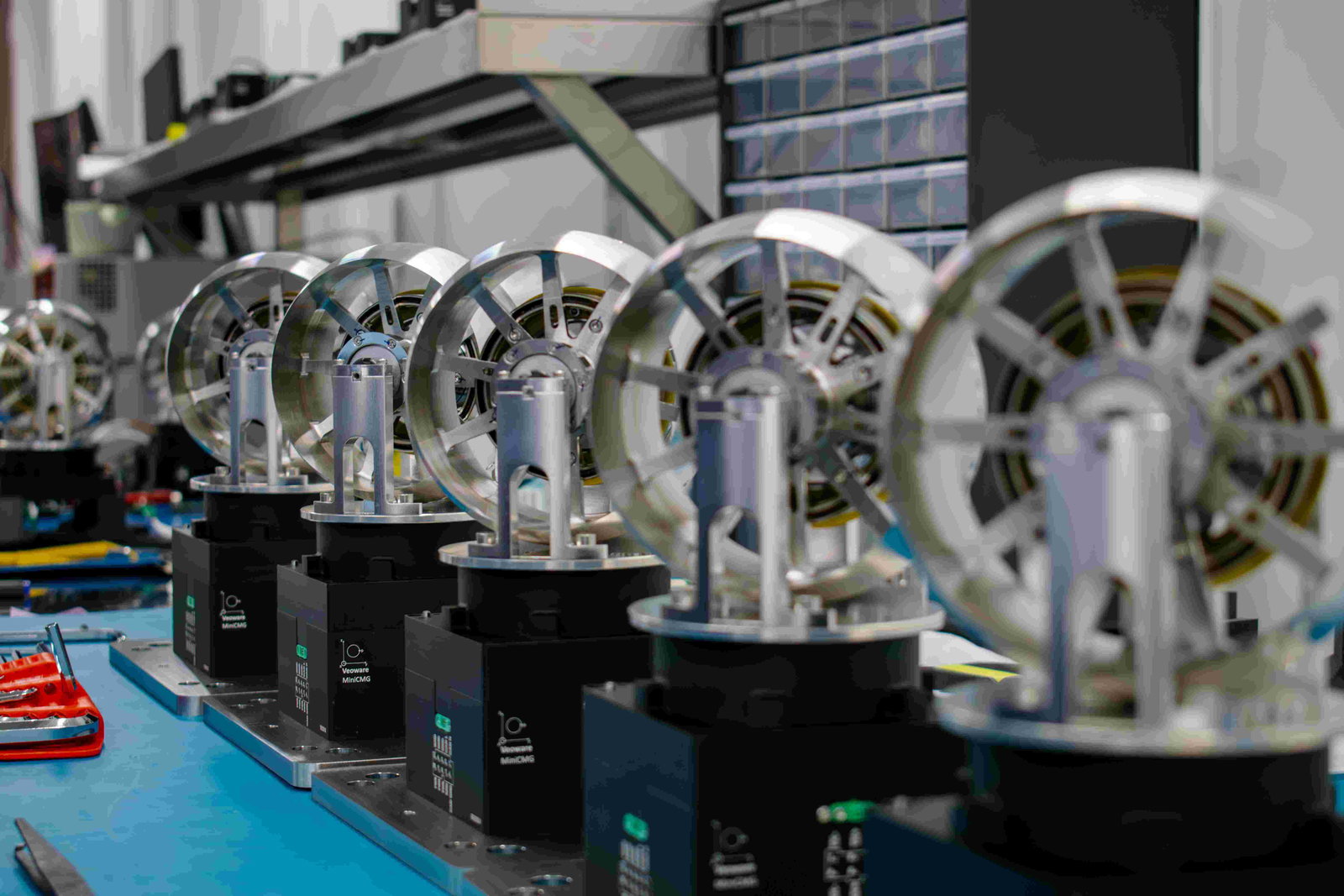
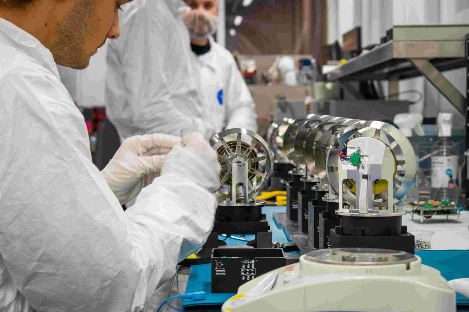
The cluster and its steering logic are designed, integrated and qualified in-house, so the model that runs on orbit matches the hardware on the bench.
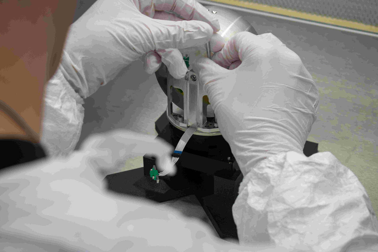
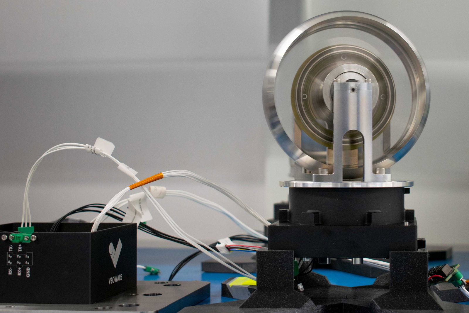
Inputs and outputs follow clearly defined cluster and body reference-frame conventions, so the system slots into your existing attitude-control architecture.
2019
2021
2023
2024
2025
2026
Send us your inertia, target list and cluster geometry, we'll size and tune the steering.